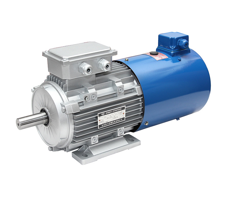
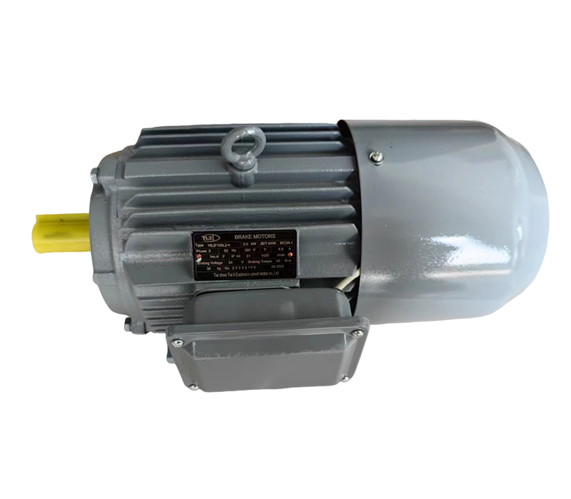
YPEJ series frequency conversion speed regulation electromagnetic braking three-phase asynchronous motor
The AC brake has a fast starting response, short braking time, and adjustable reliable braking torque
Product serial number:
Category:
Keyword: YPEJ series frequency conversion speed regulation electromagnetic braking three-phase asynchronous motor
- Product Description
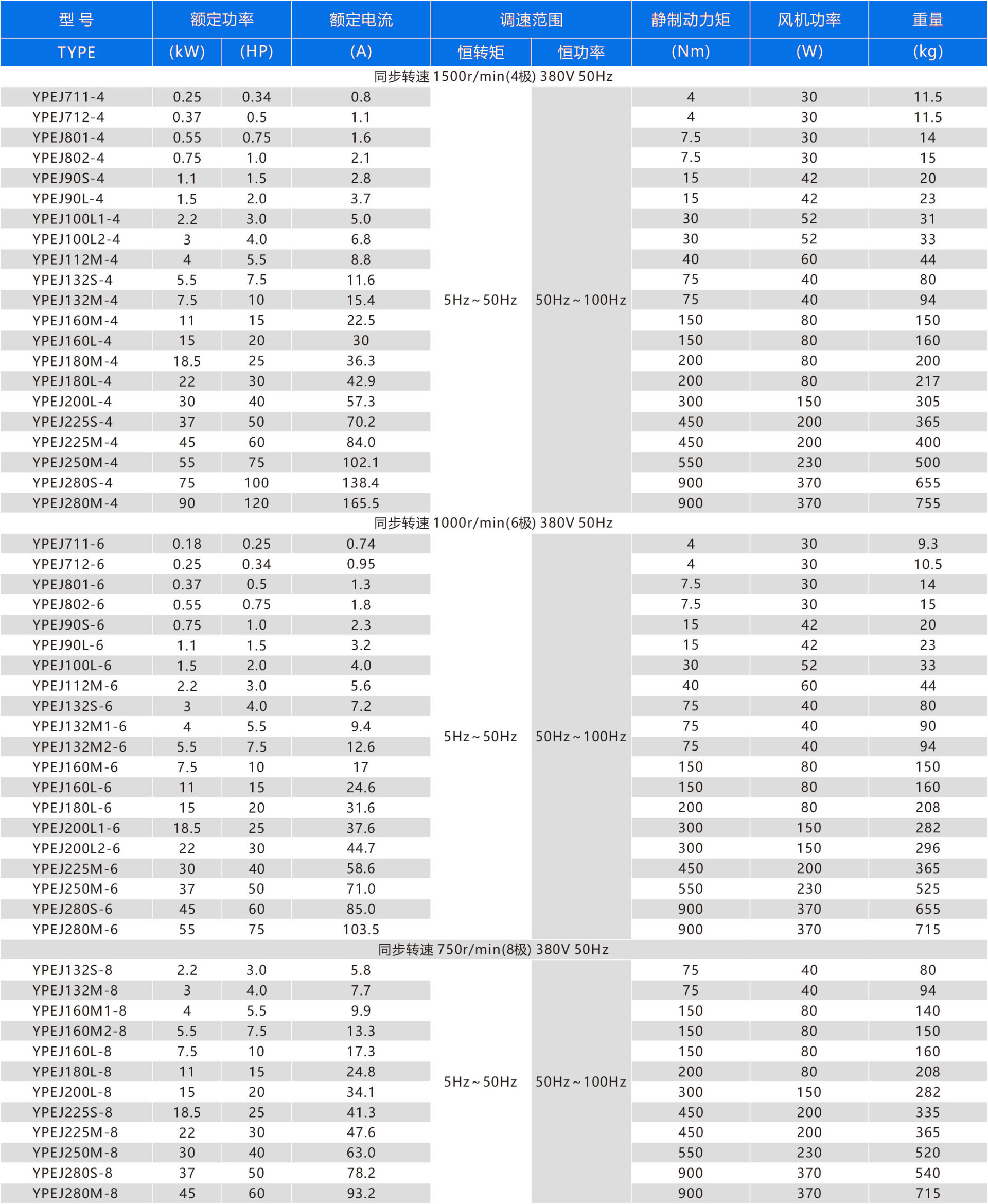
- Technical parameters
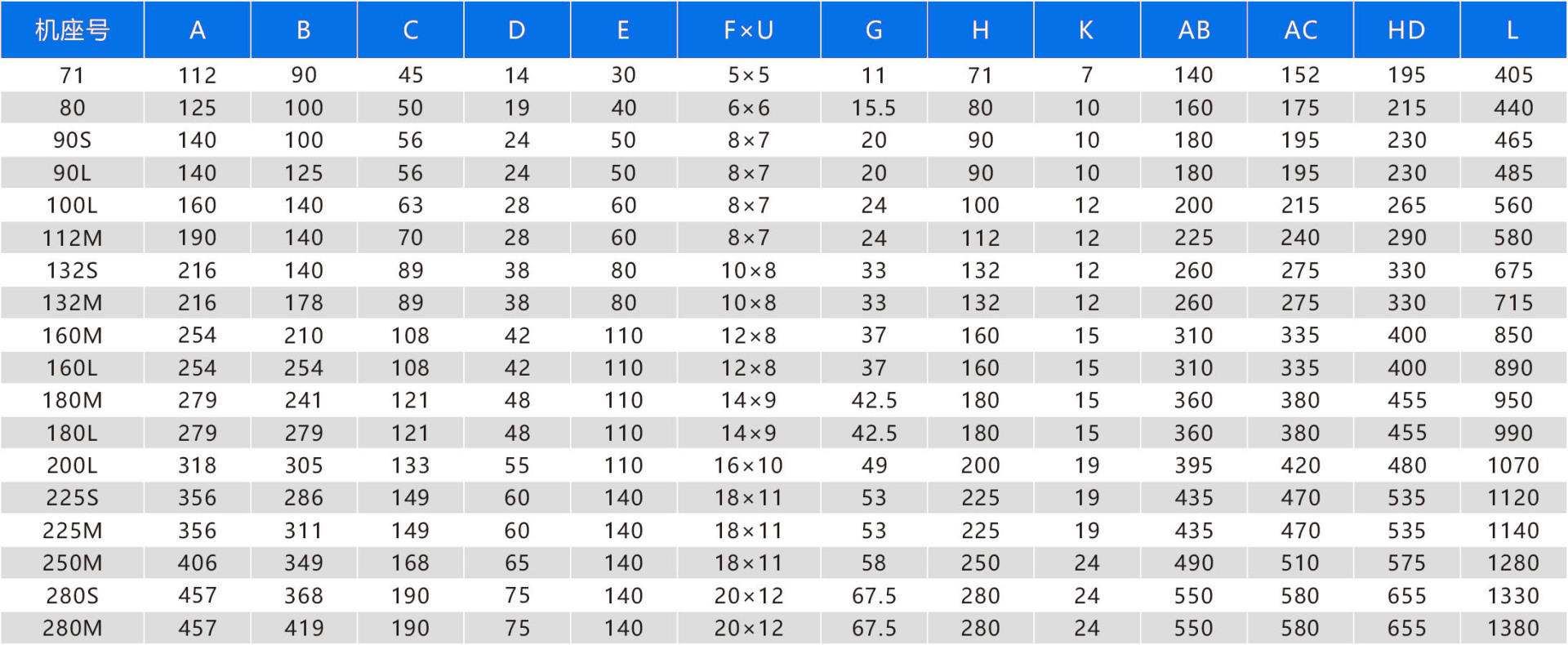
- Appearance and installation dimensions
- Wiring method
- Gap and torque adjustment
- Common faults and troubleshooting
- Sample and video download
-
- Commodity name: YPEJ series frequency conversion speed regulation electromagnetic braking three-phase asynchronous motor
Product Introduction
The YPEJ series frequency conversion speed regulating electromagnetic braking three-phase asynchronous motor is a combination of YP series frequency conversion speed regulating three-phase asynchronous motor, DZM series DC electromagnetic brake, and cooling fan. It is a motor suitable for frequency conversion speed regulation.
Application Scenarios
This series of motors is suitable for industries that require mechanical transmission, such as light industry, textiles, and electroplating production lines, to achieve speed regulation, precise positioning, and reciprocating operation.
Working Principle
When energized, the electromagnet generates a strong electromagnetic force to attract the armature plate, compressing the brake spring. The pressure between the two mating surfaces of the friction disc and the armature plate and the motor rear cover is released, allowing the motor to rotate freely. When de-energized, the brake spring pressure presses the armature plate, tightly pressing the friction disc, generating a strong frictional braking torque, and bringing the rotating motor to a quick stop for accurate positioning.
Product Features
1. The protection level of this series of products reaches IP55;
2. Motor cooling method IC416;
3. The release device is external, and manual release is flexible and convenient;
4. Insulation class F;
5. The installation dimensions and power levels of the motor fully comply with the JB/T6456 industry standard and the IEC-72 international standard;
6. The outer casing of the 71 motor is made of aluminum alloy, the outer casing of the 80~160 motor is made of aluminum alloy or cast iron, and the outer casing of the 180 and above motors is made of cast iron.
Operating Conditions
1. Rated voltage: Standard product is AC380V 50Hz;
2. Operating mode: S1 (continuous operation);
3. Altitude not exceeding 1000m;
4. Ambient temperature: -15℃~40℃;
5. When the average minimum monthly temperature is not higher than 25℃, the average maximum relative humidity in the wettest month is 95%;
6. Speed regulation range: 5Hz~50Hz is constant torque speed regulation, 50Hz~100Hz is constant speed speed regulation.
-
-

B3 type frame with feet, motor with end cap without flange

B5 type frame without feet, motor with end cap with flange (with through hole) R is the distance from the flange mating surface to the shaft shoulder
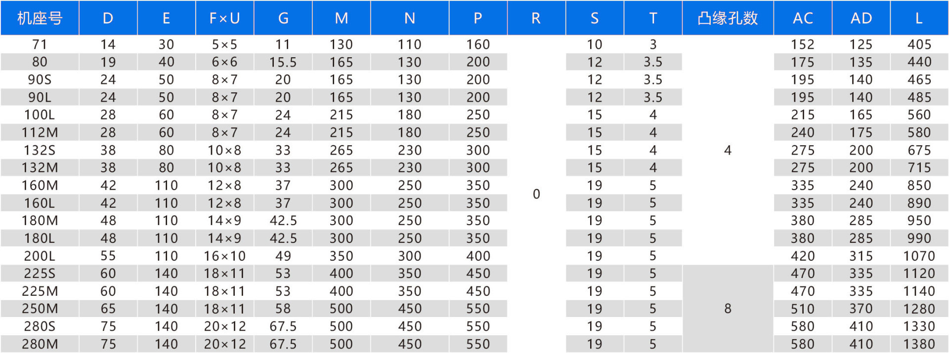

B14 type frame without feet, motor with end cap with flange (small flange with threaded holes) R is the distance from the flange mating surface to the shaft shoulder

-
1. For motors with power less than or equal to 55kW, the connection method is Y; for motors with power greater than 55kW, the connection method is Δ;
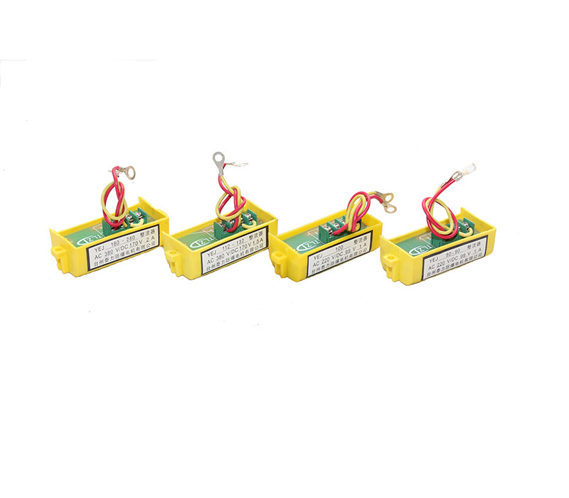
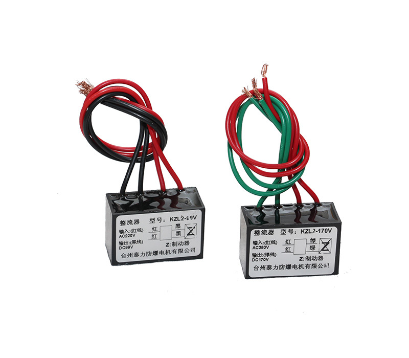
2. For the brake part, motors with machine seat number less than or equal to 100 use DC99V, and motors with machine seat number greater than or equal to 112 use DC170V;
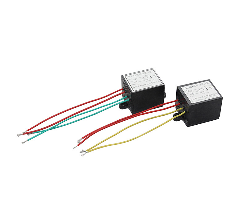
3. The quick braking connection method is as follows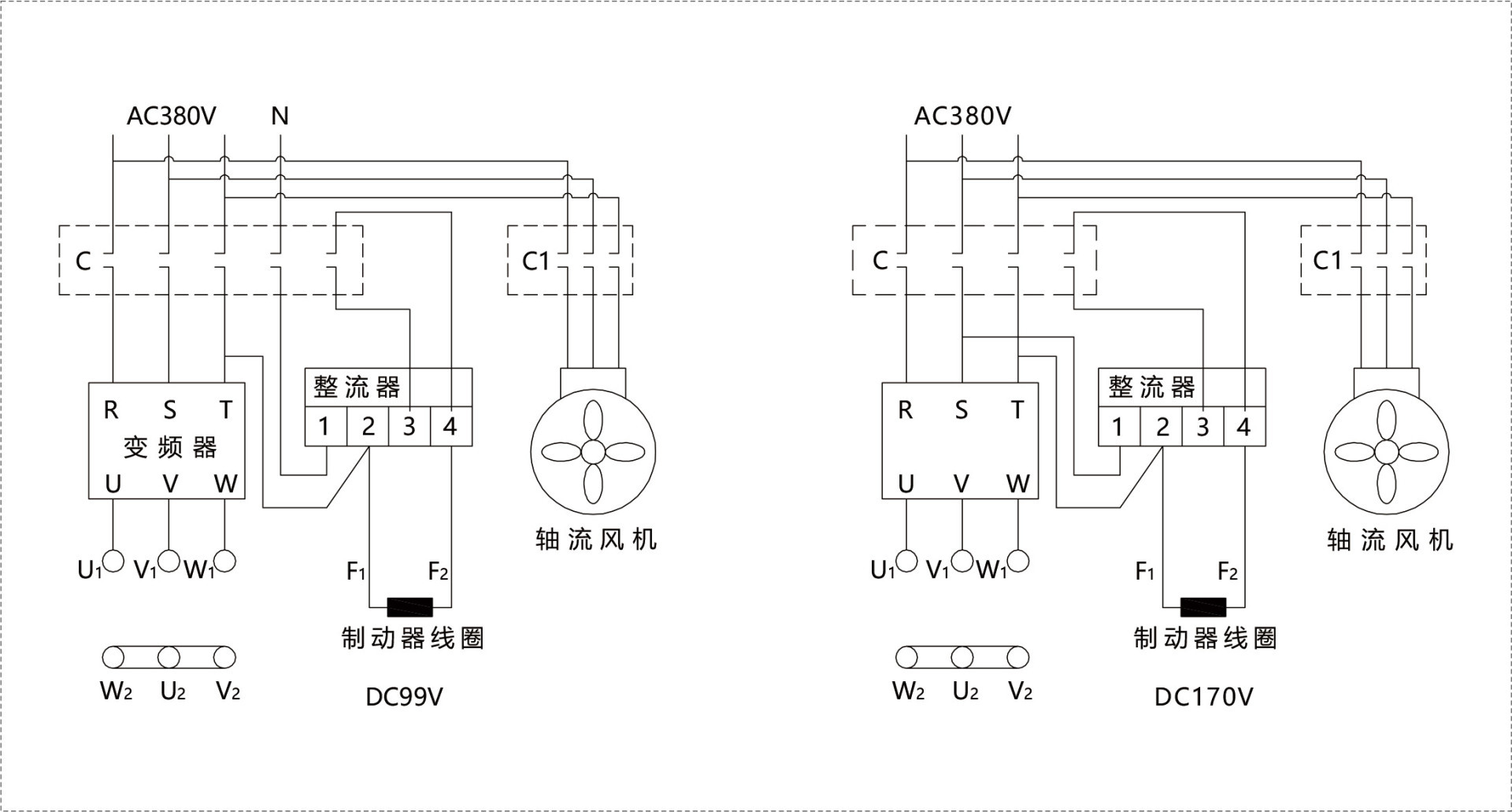
-
1. Air gap value (δ) of the brake fitted in motors of each specification in this series

2. Air gap inspection
As shown in Figure 1, the moving distance between the armature 5 and the electromagnet 6 is called the air gap (δ). The normal operating air gap (δ) does not exceed the specified air gap value. The motors are adjusted to the initial operating air gap range at the factory. After running for a period of time, the air gap value increases due to friction pad wear, which will affect the normal attraction and braking effect of the brake. Therefore, after the motor has been used for a period of time, select the feeler gauge size according to the maximum air gap value to check the size of the air gap (δ). During the inspection, the feeler gauge of the selected size can be directly inserted into the air gap (δ). If it can be inserted, it indicates that the air gap (δ) is too large and needs to be adjusted.
3. Air gap adjustment
Adjustment method for YPEJ71~YPEJ132: As shown in Figure 1, select the feeler gauge thickness according to the specified initial operating air gap value, loosen the nut 11, slightly loosen the fixing screw 13, loosen the support adjusting screw 12, place the feeler gauge into the air gap (δ) next to the loosened screw, slowly screw in the fixing screw 13, press the feeler gauge, then tighten the support adjusting screw 12 against the end cover plane, and remove the feeler gauge. There are three sets of fixing screws 13. Using the above method, adjust the air gap values on the three sides of the screws to the initial operating air gap value, ensuring the three air gap values are uniform, and then tighten the nut 11.

Adjustment method for YPEJ160 and above: Select the feeler gauge thickness according to the specified initial operating air gap value, loosen the fixing screw 13, loosen the support adjusting sleeve 9, place the feeler gauge into the air gap next to the fixing screw 13, slowly screw in the fixing screw 13, press the feeler gauge, then tighten the support adjusting sleeve 9 against the end cover (1) plane, and remove the feeler gauge. There are six sets of fixing screws 13. Using the above method, adjust the air gaps on the three sides of the screws equally spaced at 120° to the initial operating air gap value, ensuring the three air gap values are uniform, and then adjust the air gaps (δ) on the other three sides of the fixing screws, and tighten the fixing screws 13 and the support adjusting sleeve 9. After the adjustment, check the air gap with a feeler gauge to prevent uneven air gaps. If there is no feeler gauge for air gap adjustment, similar thickness iron sheet can be used instead.
-
Serial Number Fault Phenomenon Inspection Part and Method Solution Measures 1 Brake does not engage (1)Check if the air gap (δ) exceeds the air gap value;
(2)Use a multimeter to measure the resistance of the excitation coil to check for open circuit;
(3)Is the DC output power of the rectifier normal?
(4)Are the brake lead wire connectors loose?
(5)The brake has been used for a long time, and dust on the armature electromagnet surface blocks the air gap;(1)If it exceeds, readjust the air gap (δ);
(2)If there is an open circuit, repair or replace the yoke;
(3)Replace the rectifier;
(4)Retighten;
(5)After disassembling, remove foreign objects from the surface;2 Brake is ineffective and not holding firmly (1)Friction plate worn, working air gap increases, torque decreases;
(2)Friction plate damaged;
(3)Load inertia is too large, exceeding braking torque;(1)Readjust the air gap (δ);
(2)Replace with a new friction disc;
(3)Re-select motor model;3 Motor overheating (1)Overload, exceeding rated current on nameplate;
(2)Using inverter power supply, operating for too long in the low frequency range;
(3)Are there any debris like lint, yarn, or paper scraps blocking the cooling air source at the motor air inlet and on the fan blades?
(4)Check if the power supply and motor have phase loss;(1)Reduce the load, keep it within the rated load, or reconsider motor selection;
(2)Install an external auxiliary fan;
(3)Remove lint and other debris from the motor air inlet and fan blades;
(4)Repair it;4 After manual release, the shaft cannot rotate (1)Uneven air gap, armature, brake disc, and electromagnet are jammed;
(2)The friction disc is stuck by oil (from the gearbox or elsewhere);
(3)The brake has not been used for a long time, and the friction plate on the motor end cover surface is rusted stuck;(1)Readjust the air gap;
(2)Disassemble, remove the friction disc, wipe it dry, then reassemble;
(3)After disassembling, remove rust stains, reassemble, and it will work normally. -
Filename Size Upload Date Details YPEJ Series Variable Frequency Speed Control Electromagnetic Brake Three-phase Asynchronous Motor 846KB 2021/3/10 Click to download Operation Video 100M 2021/3/10 Click to download
Related Products
Message
If you have any questions, please contact us!

