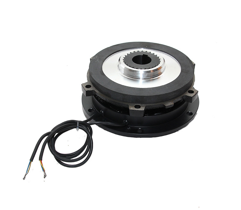
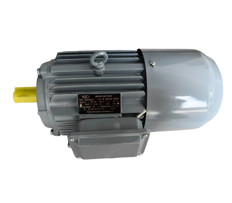
AZML series three-phase AC electromagnetic brake
The AC brake has a fast starting response, short braking time, and adjustable reliable braking torque
Product serial number:
Category:
Keyword: AZML series three-phase AC electromagnetic brake
- Product Description
- Technical parameters
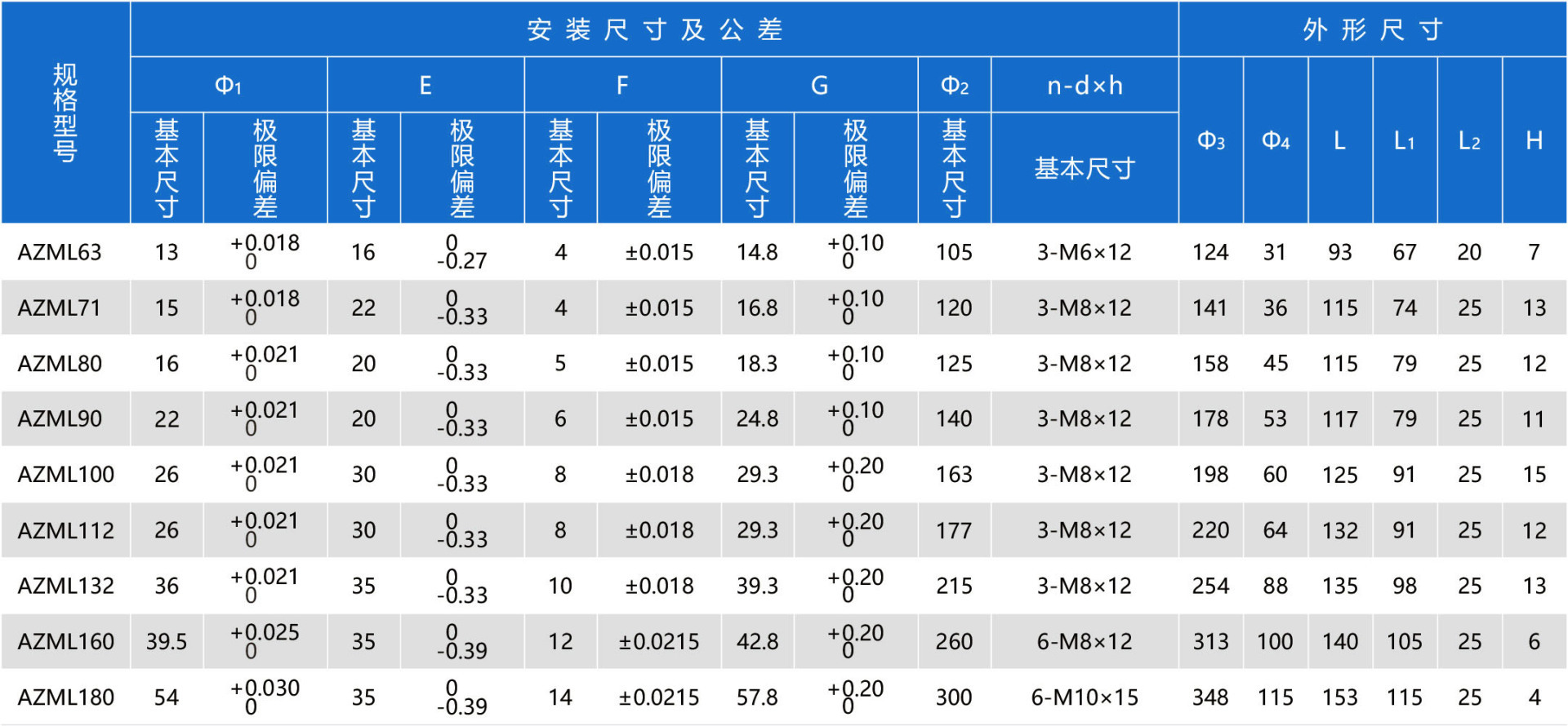
- Appearance and installation dimensions
- Installation and debugging
- Common faults and troubleshooting
- Sample and video download
-
- Commodity name: AZML series three-phase AC electromagnetic brake
Product Introduction
The AZML series (power-off type) three-phase AC electromagnetic brake is a reliable brake. The product has a compact structure, convenient and flexible manual release, and reliable performance.
The AZML series three-phase AC electromagnetic brake is matched with the Y2 series motor to form the YEJA series electromagnetic braking three-phase asynchronous motor. The motor has a beautiful appearance, fast braking, accurate positioning, and is suitable for all occasions where motors are used.
This series of products has obtained ISO9001 system certification.
Working Principle
When energized, the electromagnet generates a strong electromagnetic force to attract the armature and compress the brake spring. The two opposing surfaces of the brake disc are separated from the pressure of the armature and the motor rear cover plane, and the motor can rotate flexibly. When the power is off, the brake spring pressure is applied to the armature, pressing it tightly against the brake disc, generating a strong frictional braking torque, causing the rotating motor to brake quickly and achieve accurate positioning.
Product Features
1. Uses three-phase AC power supply, no AC/DC conversion required;
2. After assembly with the motor, the overall protection level reaches IP55;
3. Manual release is external, 63~100 is a handle, 112~180 is a hexagon socket screw, flexible and convenient;
4. Insulation class is F;
Matching Component Supply
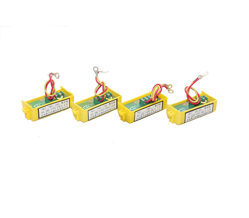
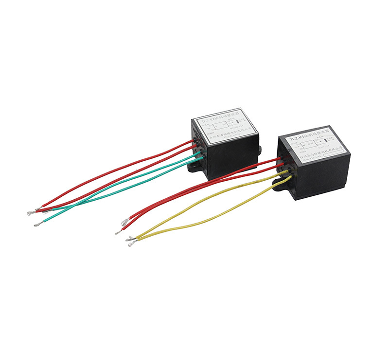
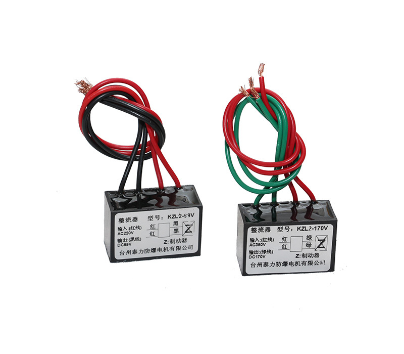
For the convenience of our customers in using the AZML series DC electromagnetic brake, in addition to providing matching rear covers, junction boxes, windshields, rectifiers and other accessories, our company also provides drawings for processing rotors of corresponding specifications. As long as they are processed according to our drawings, YEJK series braking motors can be produced.
-
-
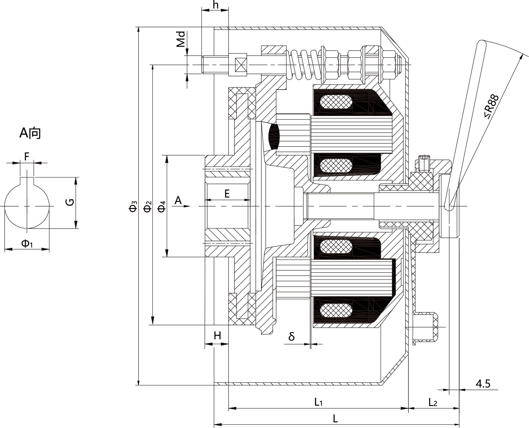
Note: Due to the excessive spring force of AZML132, 160, and 180, manual release is achieved using a hex socket screw.
-
1. Schematic diagram of the structure is as follows:
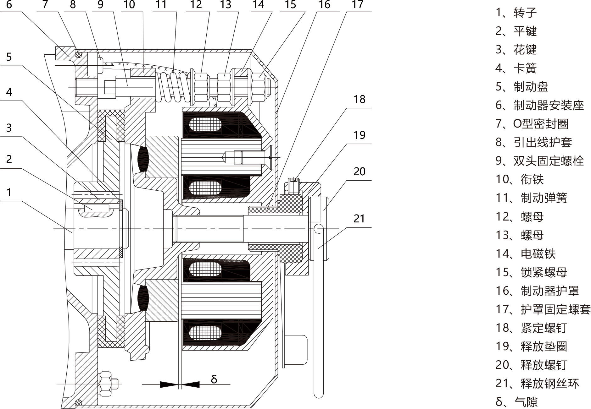
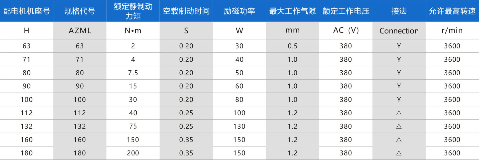
2. Brake air gap requirements

3. Air gap inspection
As shown in the structural diagram, the distance between the armature 10 and the electromagnet 14 is called the air gap (δ). The normal working air gap (δ) does not exceed the specified working air gap value. When the motor leaves the factory, it is adjusted within the initial working air gap range. After running for a period of time, due to the wear of the friction pads, the air gap (δ) becomes larger, which will affect the normal attraction and braking effect of the brake. Therefore, after the motor has been used for a period of time, according to the large air gap value, select the feeler gauge size to check the size of the air gap (δ). During the inspection, the feeler gauge can be directly inserted into the air gap (δ). If it can be inserted, it indicates that the air gap (δ) is too large and needs to be adjusted.
4. Air gap adjustment
Prepare a set of feeler gauges of different thicknesses. Select the thickness according to the initial working air gap value in the table above. Loosen the nut 13, place the feeler gauge into the gap (δ) at the edge of the loosened screw, slowly tighten the lock nut 15, press the feeler gauge, and then tighten the nut 13 outwards, and pull out the feeler gauge. Use the same method to adjust the gaps at the two screws and three screws. After adjustment, tighten the nut 13 and the lock nut 15 again, and check regularly whether the nuts are loose.
For brakes with AZML132 or higher, there are 6 sets of screws. The above method can be used to adjust three sets first, and then another three sets, at 120° intervals. The three points of the gap adjustment must be uniform, otherwise it will affect the attraction and braking of the brake, and in severe cases, it will burn out the coil.
If there is no regular feeler gauge, similar thin iron sheets can be used instead.
5. Torque adjustment
When the air gap is normal and the braking torque does not reach the rated braking torque, the three nuts 12 (six for models above 132) can be uniformly tightened forward to compress the braking spring 11, which can increase the braking torque, but not too much. It is only necessary to reach the rated braking torque on the nameplate. Too much spring pressure will cause difficulty in attraction or a harsh electromagnetic squeak, and in severe cases, it will burn out the coil. Therefore, the spring force cannot be increased indefinitely.
-
Serial No. Malfunction symptom Inspection parts and methods Solutions 1 Brake does not engage (1) Check if nut 13 is loose;
(2) Measure if the air gap (δ) is greater than the working air gap limit;
(3) Use a multimeter to measure the resistance value of the three-phase windings, check if it's basically balanced, and if there's any broken wire;
(4) Use a multimeter's AC voltage 500V range to check if there is a phase loss in the AC three-phase power input;
(5) Braking torque exceeds the rated value excessively;
(6) Check if there are any foreign objects stuck on the magnet surface or if dry grease accumulates on it, causing an uneven surface;
(7) The magnet surface becomes uneven after long-term use;(1) Tighten nut 13;
(2) Re-adjust the air gap (δ) to within the initial working air gap range;
(3) Repair broken wires or replace the magnetic yoke;
(4) If problems are found, eliminate them;
(5) Adjust the compression length of the brake spring to control the braking torque;
(6) Remove foreign objects, grease;
(7) Flatten with a lathe or surface grinder;2 Brake ineffective/doesn't hold firmly (1) Brake disc wear, increased air gap (δ), decreased torque;
(2) Brake disc damaged;
(3) Load inertia too large, exceeding braking torque;(1) Re-adjust the air gap, turn nut 4 in by half to one turn;
(2) Replace with a new brake disc;
(3) Re-select the model.3 After manual release, the rotating shaft cannot turn (1) Brake disc is stuck by oil (from gearbox or other places) (1) Disassemble and remove the brake disc, wipe it dry, then reassemble. -
File Name Size Upload Date Details AZML Series Three-Phase AC Electromagnetic Brake 791KB 2021/3/10 Click to Download Operation Video 100M 2021/3/10 Click to Download
Related Products
Message
If you have any questions, please contact us!

