AZM-B series brake
The AC brake has a fast starting response, short braking time, and adjustable reliable braking torque
Product serial number:
011
Category:
Keyword: AZM-B series brake
- Product Description
- Technical parameters
- Appearance and installation dimensions
- Installation and debugging
- Common faults and troubleshooting
- Sample and video download
-
- Commodity name: AZM-B series brake
- Commodity ID: 011
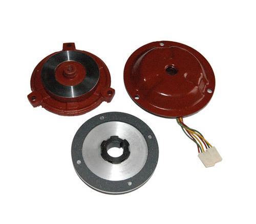
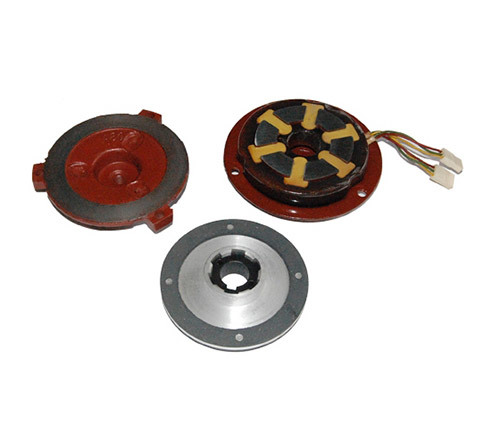
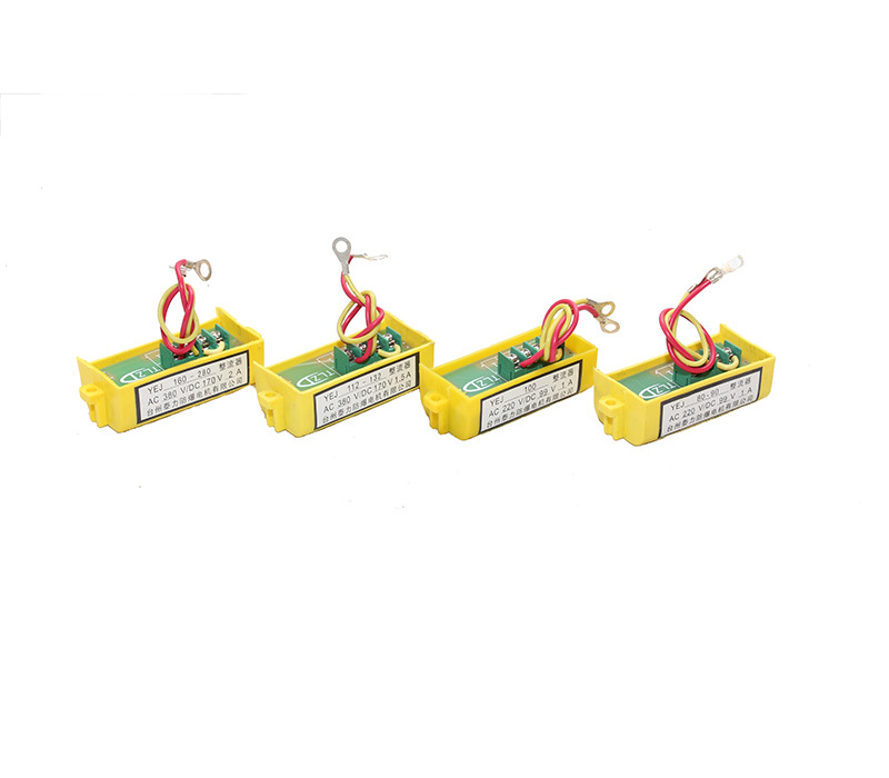
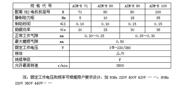
The AZM-B series (power-off braking type) three-phase AC brake is a reliable safety brake. It features a fast start-up time and a short braking time. The excitation voltage is the same as the motor, making wiring simple and operation convenient.
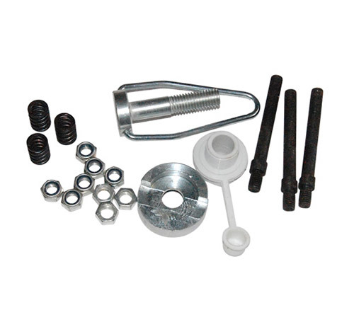
The AZM-B series three-phase AC brake has a compact structure, and the braking torque and air gap adjustment are very convenient. The manual release device has a dual function; the brake can be temporarily disengaged by gently pressing the release ring. The brake can be disengaged for an extended period by using the release screw, making operation convenient and reliable. The product's protection level can reach IP55.
The AZM-B series three-phase AC brake can be used directly with a variable frequency power supply. Frequencies below 50Hz can be used directly with a variable frequency power supply; if required, it can be designed for use with frequencies above 50Hz.
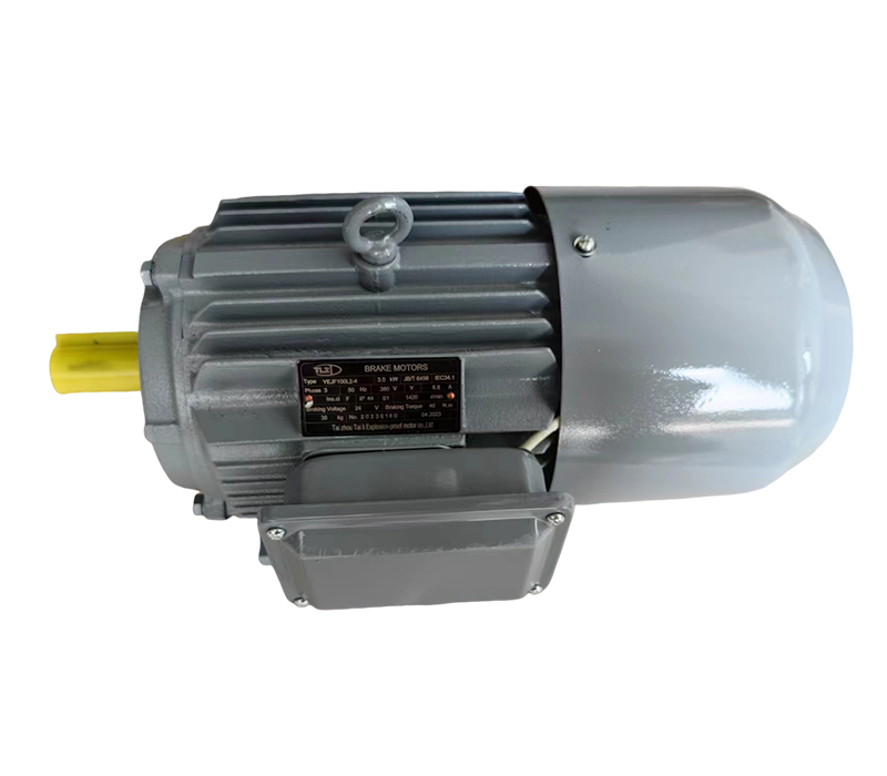
The AZM-B series three-phase AC brake fully meets the requirements for use with Y and Y2 series motors to form YEJ series electromagnetic braking three-phase asynchronous motors, and can also be used with variable frequency motors to form variable frequency braking motors. Utilizing its advantages of large braking torque, short braking time, convenient wiring, and high protection level, it can be widely used in various mechanical equipment requiring quick braking and precise positioning.
Working principle:
The AZM-B series three-phase AC brake operates as follows: When the power is off, it uses spring pressure to tightly press the armature, causing a large frictional (braking) torque between the brake disc, the armature, and the two sides of the motor's rear cover, allowing rotating objects to brake quickly; when the power is on, it uses an electromagnetic attraction release principle to release the brake disc from the braking state, allowing the object to rotate freely.
-
-

1. Spindle 2. Brake fixed end cover (seat) 3. Fixing screw 4. Cover seal 5. Brake disc 6. Armature 7. Brake spring 8. Braking torque adjustment lock nut 9. Air gap (δ) adjusting nut 10. Air gap fixing lock nut 11. Coil 12. Cover 13. Yoke 14. Cover fixing nut 15. Release screw 16. Spline 17. Key 18. Retaining ring δ, Air gap
Air gap adjustment method:
Tools: Wrench, feeler gauge
Adjustment method: Unscrew nuts and screws (14) (15), remove the cover (12), loosen 6 nuts (9) (10), select the working air gap thickness sheet according to the model of the feeler gauge, insert it near one of the fixing screws (3) δ point, screw in (10) to press the insert, then slightly retract a little, the feeler gauge can be removed, it cannot be too loose. Then, the locking nut (9) must be tightened. Use the same method to adjust the other two points 120° apart. Finally, check again whether the air gaps are the same. If they are too tight or too loose, they need to be adjusted to ensure that the three points are uniform. After long-term work, the friction pads will wear out. The δ value must be checked. If the δ value exceeds the maximum wear air gap value, it must be adjusted using the above method, otherwise it will affect the normal operation of the brake.
Precautions:
1. The armature, rear cover, and brake disc surface must be free of oil and kept dry and clean;
2. During installation and adjustment, the air gap "δ" value must be within the working air gap range;
3. The spline sleeve must not have axial movement, and a retaining ring must be added to the rear end of the spline. When assembling the brake disc, apply an appropriate amount of grease to the spline teeth.
Related Products
Message
If you have any questions, please contact us!

