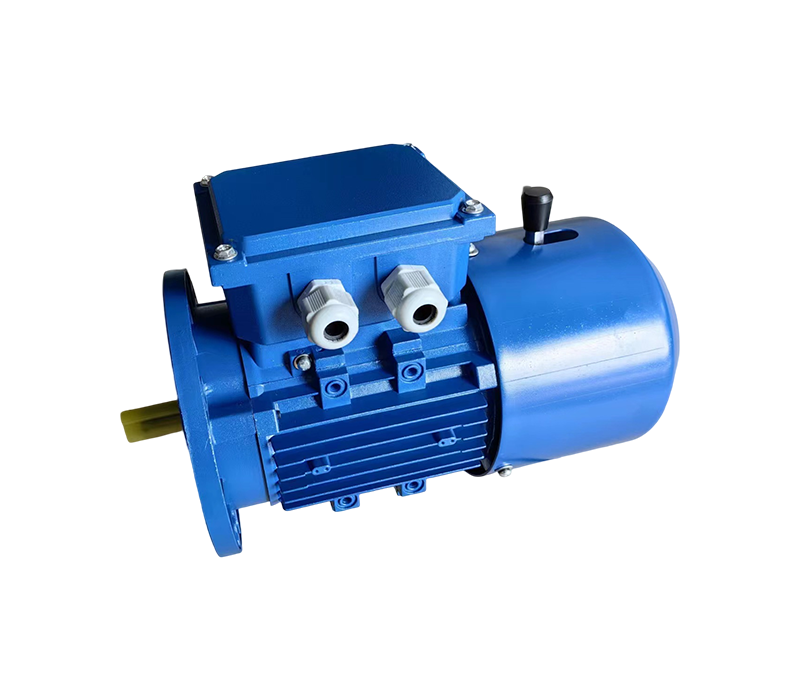
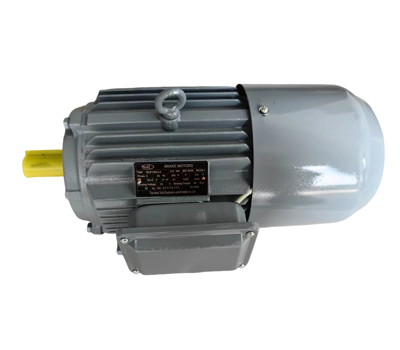
YEJK series electromagnetic braking three-phase asynchronous motor
The AC brake has a fast starting response, short braking time, and adjustable reliable braking torque
Product serial number:
Category:
Keyword: YEJK series electromagnetic braking three-phase asynchronous motor
- Product Description
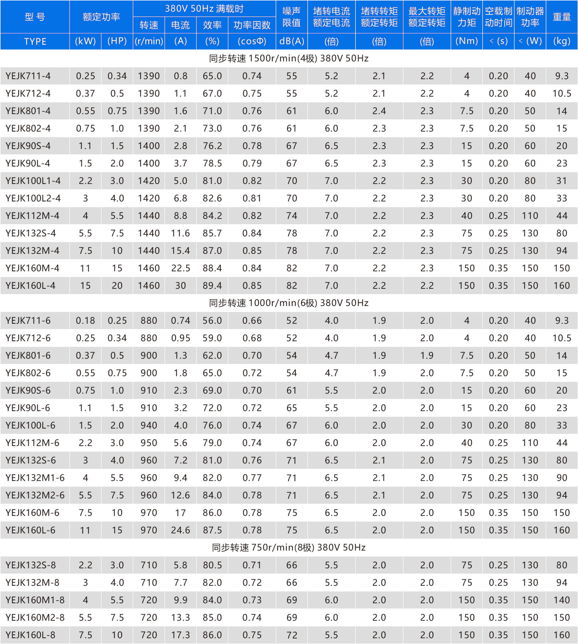
- Technical parameters
- Appearance and installation dimensions
- Wiring method
- Gap and torque adjustment
- Common faults and troubleshooting
- Sample and video download
-
- Commodity name: YEJK series electromagnetic braking three-phase asynchronous motor
Product Introduction
The YEJK series electromagnetic braking three-phase asynchronous motor is a braking motor carefully designed according to the national standard JB/T6465. It is composed of two major parts: a general-purpose Y2 series three-phase asynchronous motor and a DZK series DC electromagnetic brake. Its power rating and installation dimensions conform to the JB/T6456 industry standard and the IEC72 international standard, making it a cost-effective braking motor. This series of products has obtained ISO9001 system certification and CCC product certification.
Application Scenarios
This series of motors is suitable for environments that are not flammable, explosive, or contain corrosive gases, and are used in various machinery with requirements such as quick braking, accurate positioning, reciprocating operation, and preventing slippage, serving as the main or auxiliary drive, such as lifting machinery, transportation machinery, printing machinery, food machinery, construction machinery, woodworking machinery, deceleration machinery, and metallurgical machinery.
Working Principle
When energized, the electromagnet generates a strong electromagnetic force to attract the armature plate, compressing the brake spring. The friction disc's two opposing surfaces are released from the pressure of the armature plate and the motor's rear cover plane, allowing the motor to rotate freely. When de-energized, the brake spring pressure presses against the armature plate, tightly pressing the friction disc, generating a strong frictional braking torque, causing the rotating motor to brake quickly and achieve accurate positioning.
Product Features
1. The motor protection level is IP44, and the brake is IP23;
2. The motor cooling method is IC411 (self-ventilated);
3. The release device is an external hand lever, allowing for flexible and convenient manual release;
4. The motor insulation class is B and F, and the brake insulation class is F;
5. The motor's installation dimensions and power rating fully comply with the JB/T6456 industry standard and the IEC-72 international standard;
6. Size 71 is an aluminum-shell motor, while sizes 80-160 are aluminum-shell or cast-iron shell motors.
Operating Conditions
1. Rated voltage: Standard products are AC380V 50Hz, or can be designed according to customer requirements;
2. Operating mode: S1 (continuous operation);
3. Altitude not exceeding 1000m;
4. Ambient temperature: -15℃~40℃;
5. When the average minimum monthly temperature is not higher than 25℃, the average maximum relative humidity in the wettest month is 90%.
-
-

Electric motor with B3 type mounting base and feet, and end cap without flange


Electric motor with B5 type mounting base without feet, and end cap with flange (with through hole) R is the distance from the flange mating surface to the shaft shoulder


Electric motor with B14 type mounting base without feet, and end cap with flange (small flange with screw holes) R is the distance from the flange mating surface to the shaft shoulder

-
1. For the motor section, motors with power of 3kW and below use a Y connection upon leaving the factory, while others use a Δ connection;
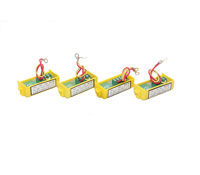
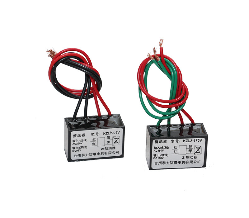
2. For the brake section, motors with a mounting base number of 100 and below use DC99V, while those with a mounting base number of 112 and above use DC170V.The connection method for a motor with a Y connection and a DC99V brake is as follows:

The motor uses a Δ connection, and the connection method for a DC170V brake is as follows:

The connection method for a motor with a Y connection and a DC170V brake is as follows:

-
1. Air gap value (δ) of the brake fitted in motors of each specification in this series

2. Air gap inspection
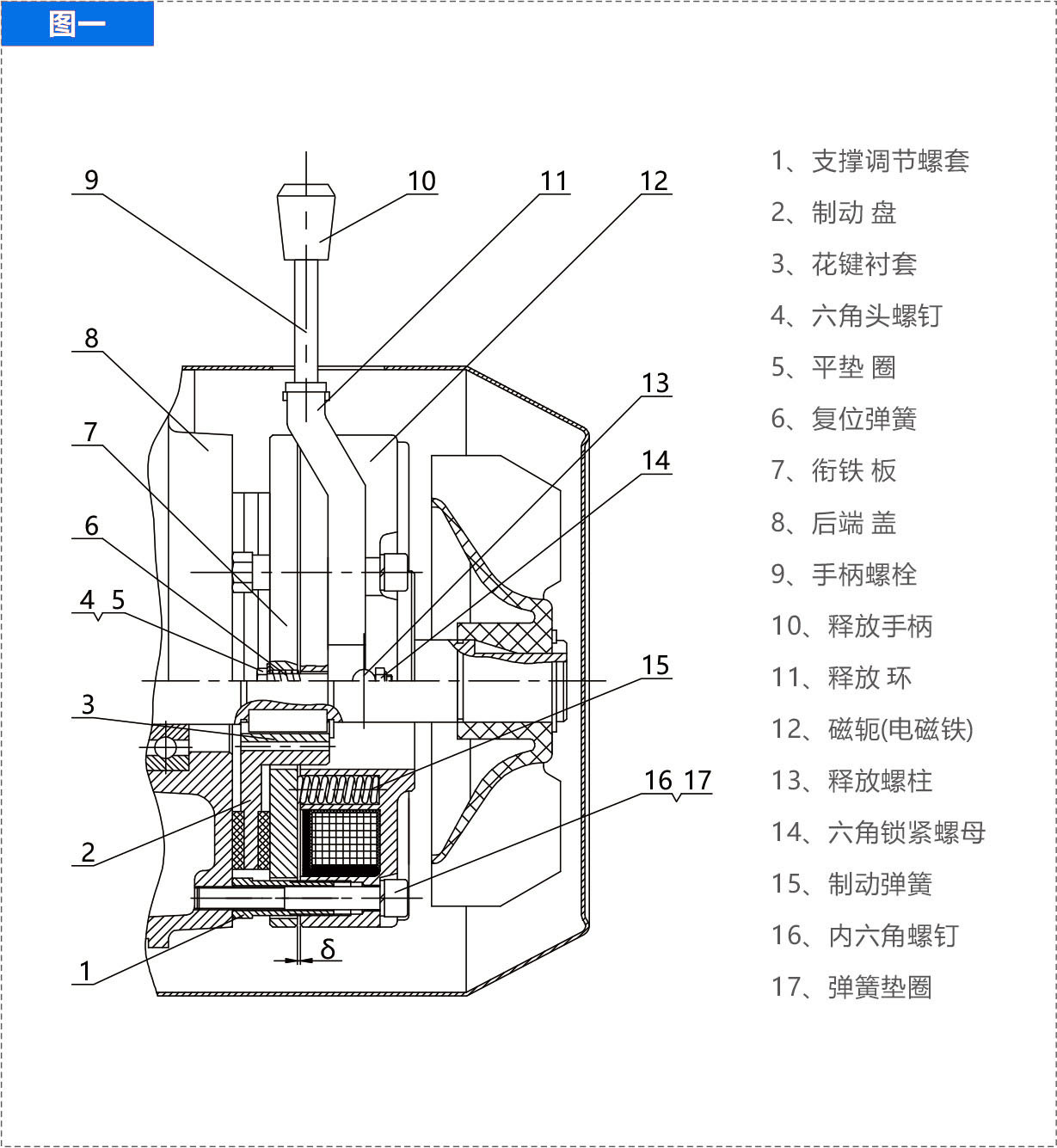
As shown in Figure 1, the moving distance between the armature 7 and the electromagnet 12 is called the air gap (δ). The normal operating air gap (δ) does not exceed the specified air gap value. When the motor leaves the factory, it is adjusted to the initial operating air gap range. After running for a period of time, the air gap value increases due to friction pad wear, which will affect the normal attraction and braking effect of the brake. Therefore, after the motor has been used for a period of time, select the feeler gauge size according to the maximum air gap value to check the size of the air gap (δ). During the inspection, the feeler gauge of the selected size can be directly inserted into the air gap (δ). If it can be inserted, it indicates that the air gap (δ) is too large and needs to be adjusted.
3. Air gap adjustment
Prepare a set of feeler gauges. Select the thickness according to the initial operating air gap value in Table 1. As shown in Figure 1, loosen the nut 5, place the feeler gauge into the air gap (δ) at the edge of the loosened screw, slowly tighten the lock nut 7, press the feeler gauge, then tighten the nut 5 outwards, and remove the feeler gauge. Use the same method to adjust the air gap at the second and third screws. After adjustment, tighten the nut 5 and the lock nut 7 again, and check regularly for loose nuts.
The brake screws of YEJA132 and above motors have 6 sets. Following the above method, adjust three sets first at 120° intervals, then adjust the other three sets. The three points of air gap adjustment must be uniform, otherwise it will affect the attraction and braking of the brake, and in severe cases, it will burn out the coil. If there is no regular feeler gauge, similar thickness iron sheet can be used instead.
4. Torque adjustment
Select the feeler gauge thickness according to the specified initial operating air gap value. As shown in Figure 1, loosen the hexagon socket screw 16, turn the support adjusting sleeve 1 towards the electromagnet by 1-2mm to facilitate air gap adjustment, place the feeler gauge into the air gap (δ) next to the support adjusting bolt, slowly tighten the hexagon socket screw 16, press the feeler gauge, then press the support adjusting sleeve 1 against the end cover 8 plane, and remove the feeler gauge. The DZK04-75 fixed hexagon socket screw 16 has three sets. Adjust the air gap values on the three sides of the screws to the initial operating air gap value using the above method. The three air gap values must be uniform, and then tighten the hexagon socket screw 16. The DZK150 fixed hexagon socket screw 16 has four sets. The adjustment method is the same as above, generally adjusting the diagonal screws first. After adjustment, check the air gap with a feeler gauge to prevent uneven air gap. If there is no standard feeler gauge for air gap adjustment, similar thickness iron sheet can be used instead.
-
Serial No Fault Phenomenon Inspection Parts and Methods Solutions 1 Brake does not engage (1) Check if the air gap (δ) exceeds the specified air gap value;
(2) Measure the resistance of the excitation coil with a multimeter to check for an open circuit;
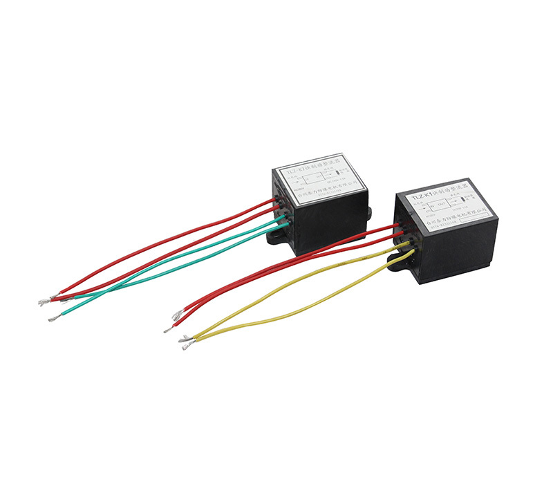
(3) Is the DC output power supply of the rectifier normal?
(4) Are the brake lead wire connectors loose?
(5) After long-term use of the brake, dust clogs the air gap on the surfaces of the armature and electromagnet;(1) If exceeded, readjust the air gap;
(2) If there is an open circuit, repair or replace the magnetic yoke;
(3) Replace the rectifier;
(4) Retighten;
(5) After disassembly, remove foreign matter from the surface;2 Brake ineffective / Brake not holding (1) Friction plate worn, working air gap increased, torque decreased;
(2) Friction plate damaged;
(3) Load inertia too large, exceeding braking torque;(1) Readjust the air gap (δ);
(2) Replace with a new friction disc;
(3) Re-select motor model;3 Motor overheating (1) Overload, exceeding the rated current specified on the nameplate;
(2) Using inverter power supply, operating for too long in the low-frequency range;
(3) Is there any foreign matter like cotton wool, yarn, or paper debris blocking the cooling air source at the motor air inlet and on the fan blades?
(4) Check if the power supply and motor have phase loss;(1) Reduce the load, keep it within the rated load, or reconsider motor selection;
(2) Install an external auxiliary fan;
(3) Remove foreign matter like cotton wool from the motor air inlet and fan blades;
(4) Provide repair;4 Shaft cannot rotate after manual release (1) Uneven air gap, armature, brake disc, and electromagnet are jammed;
(2) Friction disc is stuck by oil (from gearbox or other sources);
(3) Brake not used for a long time, motor end cover flat friction plate rusted solid;(1) Readjust the air gap;
(2) Disassemble, remove the friction disc, wipe it dry, and then reassemble;
(3) After disassembly, remove rust spots, reassemble, and it will work normally -
File Name Size Upload Date Details YEJK Series Electromagnetic Braking Three-Phase Asynchronous Motor 819KB 2021/3/10 Click to Download Operation Video 100M 2021/3/10 Click to Download
Related Products
Message
If you have any questions, please contact us!

